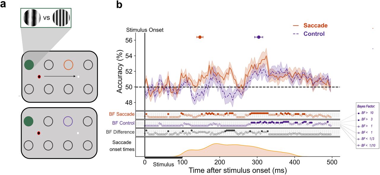
Earlier decoding of SF at the remapped location with a saccade. This figure illustrates the difference between decoding at the remapped location with and without a saccade. In panel a, the circles represent possible stimulus presentation locations and an example configuration of train and test locations for the classification of saccade trials (top panel) and control trials (bottom panel). The green-filled circle represents the location on which the classifier was trained, and the orange and purple circles signify the test locations for saccade and control trials, respectively. The red ring signifies current fixation. The gratings illustrate stimuli at low and high SF. b, The mean classification over time for classifiers trained on fixation trials and tested on either saccade trials (orange) or control (purple) trials. The plotted results reflect the average performance at corresponding training and testing timepoints. All decoding results are averaged over classifiers, across left and right fixation, and subsequently, across subjects. The shaded areas depict the standard error of the mean across subjects. Above-chance decoding onsets are plotted with 95% confidence intervals. The Bayes factors (BF) below the plots indicate the timepoints at which there was substantial evidence in favor of the alternative hypothesis, i.e., decoding above-chance (filled circles). Timepoints at which there was not enough evidence or substantial evidence for the null hypothesis, i.e., chance level, are indicated by open circles. The distribution of saccade onset times is plotted below.